TECHNICAL SCOPE OF FUNCTIONAL CLAIM LANGUAGES BE DETERMINED IN LIGHT OF WHETHER PERSON SKILLED COULD HAVE DEDUCTED THE ACCUSED STRUCTURE FROM THE PATENT SPECIFICATION
IP Court Case Summary:H23(Wa)10341
On November 8, 2012, the Osaka district court issued a non-infringement decision in which the court said that a technical scope of the functional claim languages should be determined in light of whether a person skilled in the art could have deducted from the disclosures in the specification.
The invention was directed to an antitheft device which prevents computers against theft. [i] The following are illustrative of the invention at issue.
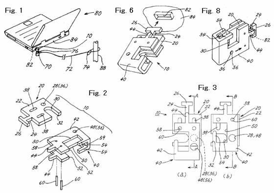
The antitheft device or connector (10) has a portion that is adapted to be inserted into an antitheft slot (82) defined in a body casing (84) of, for example, a personal computer (80). The connector (10) comprises a main plate (20) and an auxiliary plate (40) that are slidably engaged and detachably retained with one another in an insertion direction into the slot (82). The main plate (20) comprises a base plate (22), an insertion portion (24), and a retaining portion (26) provided at a distal end of the insertion portion (24) and projected laterally outwardly therefrom. The auxiliary plate (40) comprises a slide plate (42) which is engaged with the main plate (20) in a manner such that the slide plate (42) is slidable in a projecting direction of the insertion portion (24), and an anti-rotation portion (44) which is projected so that the anti-rotation portion ’44) is brought into an overlapping position with the insertion portion (24) by a sliding movement of the slide plate (42) in the projecting direction and out of the overlapping position by a sliding movement of the slide plate (42) in the opposite direction. The main and auxiliary plates (20, 40) are provided with engaging portions or apertures (28, 48) formed in respective positions such that, when auxiliary plate (40) is slidingly forwarded with respect to the main plate (40) to overlap the anti-rotation portion (44) with the insertion portion (24), the main and auxiliary plates correspond to each other.
The accused device is also directed to an antitheft device for use with computers. The following are illustrative of the accused device.
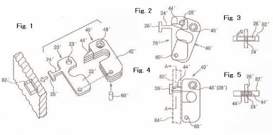
The device comprises main and auxiliary plates (20′, 40′) pivotably connected with each other by shaft (60′). This cause that the auxiliary plate (40′) pivots about the shaft (60′) with respect to the main plate (20′) so that the auxiliary plate (40′) takes an un-overlapped position where anti-rotation portion (44′) of the auxiliary plate (40′) does not overlap with the insertion portion (24′) of the main plate (20′) (see Figs. 2 and 3) to allow the inserted device to rotate with respect to the computer and an overlapped position where the anti-rotation portion (44′) overlaps with the insertion portion (24′) (see Figs. 4 and 5) to prevent the inserted device from rotating with respect to the body of the computer.
At issue was a construction of functional language “slidably engaged and detachably retained”. In this regard, the court said as follows: “The claim language “slidably engaged and detachably retained” is functional and abstract, so that, if all the structures with the same function or effect were to fall within its technical scope of invention, structures not disclosed in the specification could be included within the technical scope of the invention. Therefore, as to the functional claim, the technical scope of the invention should be determined on the basis of the technical thought provided in the specific structures disclosed in the claims and/or the specification. Also, structures that a person skilled in the art could deduct easily from the content disclosed in the specification might be said to fall within the technical scope of the invention, but structures that a person skilled in the art could not deduct easily from the content disclosed in the specification should not fall within the technical scope of the invention because it is based upon a different technical thought.”
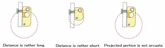
In this regard, the court admitted that no prior art in the same technical field discloses a structure in which two members or plates (main and auxiliary plates) are pivottably connected by a shaft. Also, the court admitted that an employment of the accused pivot connection requires further considerations on a distance between the pivot shaft and the projected portion and a shape of the projected portion. Otherwise, the auxiliary plate may not be slidable with respect to the main pate. Specifically, in the accused device, the pivot shaft is appropriately spaced away from the projected portion and the outer periphery of the projected portion has an appropriate arcuate configuration so that the projected portion moves in an arcuate path about the shaft to insert into the slot. To explain this, the decision includes following drawings.
In view of foregoing, the court said that
(i) it can not be said that the structure of the accused device is the one that a person skilled in the art could have been deducted easily from the disclosures of the present specification in view of the technical common sense and/or known technology; and
(ii) the technical thought disclosed in the present invention is that the slidably engaged and detachably retained structure is accomplished by forming in one plate an elongate through-hole extending in the sliding direction and securely mounting a pin in the other plate and engaging the pin in the elongate hole.
In conclusion, the court decided that the accused device employs a specific structure that is different in principle from the structure disclosed in the present application to attain the slidably engaged and detachably retained structure and therefore does not constitute an infringement.
http://www.courts.go.jp/hanrei/pdf/20121116134220.pdf
________________________________________
[i] Claim 1 reads:
An antitheft connector which is adapted to be inserted into an antitheft slot defined in a body casing (84) of, for example, a personal computer (80), characterized in that a main plate (20) and an auxiliary plate (40) are slidably engaged and detachably retained with one another in an insertion direction into the slot (82); the main plate (20) comprises a base plate (22), an insertion portion (24), and a retaining portion (26) provided at a distal end of the insertion portion (24) and projected laterally outwardly therefrom;
the auxiliary plate (40) comprises a slide plate (42) which is engaged with the main plate (20) in a manner such that the slide plate (42) is slidable in a projecting direction of the insertion portion (24), and an anti-rotation portion (44) which is projected so that the anti-rotation portion ’44) is brought into an overlapping position with the insertion portion (24) by a sliding movement of the slide plate (42) in the projecting direction and out of the overlapping position by a sliding movement of the slide plate (42) in the opposite direction; and
the main and auxiliary plates (20, 40) are provided with engaging portions (28, 48) formed in respective positions such that, when auxiliary plate (40) is slidingly forwarded with respect to the main plate (40) to overlap the anti-rotation portion (44) with the insertion portion (24), the main and auxiliary plates correspond to each other.